|
Caprice-9C1 Fan Delete
For 91-96 B-Bodies
by Bob Ignash
bnbignash@voyager.net
If you are one of the many Caprice or 9C1 owners who are tired of the
roar of the mechanical fan, which robs you of HP and gets in your way
when you are working on your car, then here is how I made the change
to the factory electric fan.
1. Removal:
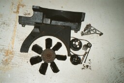
Remove the Mechanical fan and mounting hardware. Remove the top fan
shroud. There are bolts along the top of the radiator and down along
the side that connect it to the lower half of the shroud.
Remove the 4 nuts that hold the fan blade on and
remove the fan and pulley. From the underside of the car, remove the 2
bolts that hold the lower half of the shroud on and remove the shroud.
The bracket that holds the idler on is held on by three of the water
pump bolts. They will need to be removed along with the bracket.
Replace the bolts with shorter 3/8x16x4 bolts. They can be bought at
any hardware store. Use thread sealer on the threads.
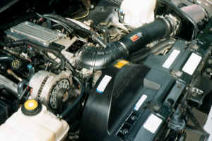
Replace the upper fan cover with one from an Impala
or Caprice with dual electric fans (GM part # 10281082= $9.09). All
prices for parts are prices I got from GM parts direct. Install the
electric fan unit. It is held on by a slot on the bottom and a screw
on the top and side. I found it easier to remove the screws on the
other fan to match them up for size. There is a long one on top and a
short one on the side. If you are buying a new fan they come in three
pieces.
Motor part # 22137318 = $47.25
Fan Kit part # 12365300 = $48.50
Motor kit part # 22135365 = $57.50
You will also want to remove the crankshaft fan pulley...Just 3 bolts.
2. Wiring:
Start by disconnecting the battery. Then remove the power supply
"large cable" from the underhood fuse box. Disconnect the plug in
connector on the back side of the box. This is done only to make it
easier to work on. Remove the bolts that hold the box in place. The
box is actually a box within a box. To separate them, find the
retaining clips that are located between the walls of the box and
remove the outer shell. Now you can get to the wires on the back of
the fuse box. Using the diagram on the lid of the fuse box, locate the
empty 40 amp fuse position for the primary fan. Using 10 gauge wire
and a female spade connection, insert from the bottom of the fuse box,
the connector into the unused side of the fuse connection. You may
need to enlarge the slot a little to insert the connector. The other
side is switched power. Install a 40 amp Maxie fuse. Run enough wire
to go where your relay is going to be mounted. The fender well is a
good location. Now using the diagram on the lid of the under hood fuse
box, locate the 10 amp fuse labeled primary fan. Connect a 14 gauge
wire to the fused side, to the location where the relay will be
mounted. Reassemble the two parts of the fuse box; neatly route the
wires. Reconnect the power supply cable to the under hood fuse box and
reconnect the plug on the back.
3. Wire the PCM:
Connect PCM pin, Part # 12084913, $1.11 to a roll of 20 gauge wire.
Remove the Red 32 pin connector from the PCM. Open the plastic cover
over the wires. There are 3 little plastic tabs that allow you to do
that. Insert, "Push" the pin into position # 11. They are numbered on
the connector. That is the ground signal from the PCM to turn on the
relay. You can see that the pin goes all the way in as it is made of
clear plastic. Reinstall the connector on the PCM. Route the wire to
the location of the relay.
4. Wiring the relay:
Mount a 30 amp relay to your fender well. Four position relays are
labeled by numbers. Numbers 30-85-86-87. At # 30, you will connect the
10 gauge wire that you have coming from the 40 amp fuse from the under
hood fuse box. At 85, you will connect the 14 gauge wire you have
coming from the 10 amp fused position in the underhood fuse box. At #
86, you will connect the 20 gauge wire from the PCM. At # 87, you will
run a 10 gauge wire to the positive side of the fan motor. From the
negative side of the fan motor, you will need to run a 10 gauge wire
to a good ground. There is a ground just in front of the battery that
is easy to reach. If you can find a plug connector for the fan,
perhaps at a junk yard, it will look much nicer. If not, you can use
insolated spade connectors.
Be sure to check all wiring and perform a complete
test of the system prior to operation. I hold no responsibility for
this modification. It has worked great for me. The primary and
secondary fan come on independently of each other at the predetermined
temperature programmed into the PCM. The roar of the old mechanical
fan is gone. Vibration from the fan is gone. Getting to areas in front
of the engine are made much easier. Plus it frees up some wasted HP. |