|
Source:
http://www.radford.edu/~aarant/overheadinstall.htm
By: David Langness, John "AK" Snyder, and Ed Runnion with input
from various other members of the
NAISSO Digest
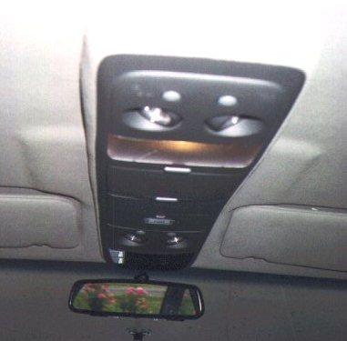
Console as
installed in David Smith's 96 SS
Parts Required :
- Astrovan
Overhead Console, which most of us have been purchasing on an
EXCELLENT deal from
David Langness.
- Ambient Temp
Sensor : PN 15971127 (Approx $12). You MUST use the sensor under
this part number, as even though the one for the Buick Roadmaster
will plug in it does NOT have the correct resistance calibration for
the Astrovan Console display unit! Thanks to Brian Steyer for
helping me figure this out.
- Figure on approx
100 ft (total) of 18GA stranded hook-up wire, preferably (if you can
get it) split approximately evenly among these colors :
- Red
- Orange
- Green
- Purple
- Black
- White
The color split of
course is not necessary, but should make it easier to keep track of
all the wires.
- Misc electrical
connectors, solder, electrical tape, heat shrink tubing, tie-wraps,
etc.
- Approx 10 sheet
metal screws, 10x1.5" and 10x2".
- Silicone caulk
(SMALL amount)
- 3 or 4 wire
connector (insulated, a trailer lighting connector works fine)
- Trim Adhesive
(3M)
- OPTIONAL : Rivnut
tool and rivnuts
- Other misc
hardware to fabricate brackets (i.e. .080 sheet aluminum) as
necessary
References / Thanks
:
- 1996 Impala SS
FSM (Factory Service Manual) pages :
- 8A-202-0 thru
8A-202-2
- 8A-68-0
- 8A-63-0
- 8A-150-0 thru
8A-150-7
- Pages from 1997
Astrovan FSM dealing with the overhead console
A GIF that
Bill Calcagno of the Syclone/Typhoon
list kindly gave me that shows how a similar console is wired in the
Typhoon.
Voltmeter probings that I did on HAIL/NAISSO Member
Ron Grant's
rental Astrovan :^), as well as wire color confirmations to the
Astrovan wiring diagram.
Conversations with MANY Impala SS owners, including Dick Sigrist,
Scott Pietzsch, Bill Clisby, Mike Allendorfer, and Scott Mueller
among others.
Excellent Installed Pictures from David Smith.
Directions :
- DISCONNECT THE
VEHICLE BATTERY. Nothing ruins a day like shorting out major
portions of your car electrical system :^).
- Remove the dome
light -- the cover snaps off with a little pressure from front and
back, the base pulls out, and the two-wire clip pulls off.
- Remove the Left
sunvisor (3 screws)
- Remove the left
A-pillar trim (it just "pulls" out, is held in by two clips)
- Remove the lower
dash by doing the following :
- First you must
remove the dash. Start by opening the glovebox, ashtray, and
drivers door, and remove the fuse panel cover.
- Remove the four
screws holding in the ashtray. Pull it out, and unplug the light.
- Remove the
black bezel around the speedo cluster. It is two screws pointed
up, then pull it out to disengage it from the "prongs" holding it
to the grey plastic below.
- Remove the
following screws :
- One on the
left side beneath the black cluster bezel removed above.
- Similar screw
in the "fuse panel" that is screwed into the side of the air
vent
- Total of 4
screws along the bottom of the dash pointed straight up.
- One screw
pointed straight up that is inside the "ashtray area" basically
below the right side of the radio.
- Now just YANK
on the panel, it should come loose from the prongs holding it in
and practically fall in your lap! Installation is the reverse of
removal.
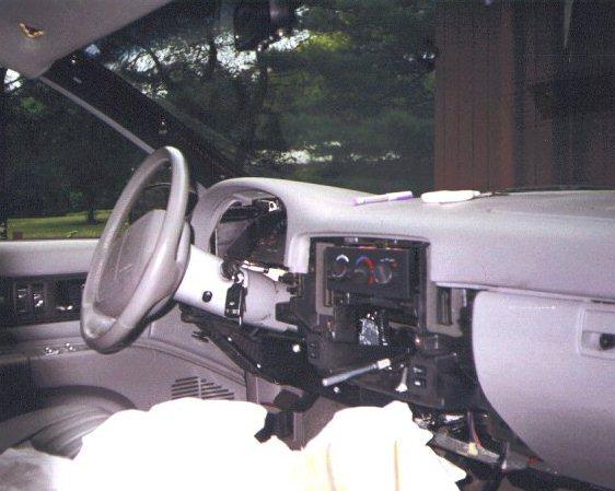
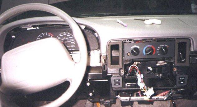
Lower Dash,
Sunvisor, Left A-Pillar Trim, and Radio Removed in David Smith's SS
- Remove the radio,
but only AFTER you have written down (or remember) the "theftlock"
code in the radio if you have it set. Radio is removed by removing
the two screws holding it in from the front (will be obvious once
the lower dash is off) and pulling it out. Unplug the 20-pin
connector and antenna from the radio. Procedure to set this code is
located in your Owner's Manual.
- Disassemble the
console base from the main body -- turn it upside down and back out
about 12 T-10 torx-head screws. Open the cd holder door all the way
and separate the two pieces. At this time, remove the 6-wire harness
from the console that runs from front to back (plugs into the
display at the front, and has a dangling blue connector at the
back).
- Now is the time
to build your wiring harness for the console display. To do this,
take the 6-wire harness from the step above, and cut all the wires
approx 6-12" from the BLACK connector on the harness. Also, cut off
the BLUE connector at this time (approximately 6 inches from the
connector) and set it aside for later
Cut off FIVE 8-FOOT lengths of the 18ga hookup wire, and also ONE
12-FOOT length of wire. If you are lucky enough to have the wire in
the various colors listed above, cut the 12-foot length from the
PURPLE wire and 8-foot lengths from all the other colors (one length
of each color). Solder in the wire lengths to the matching color on
your split harness (i.e. the connector plus 6-12") and the other
ends of the wire lengths to the SAME COLOR from what you cut off
above. When you finish, you will have the original black/red
connector with 5 wires that are approx 10.5 feet in length (8 feet +
2.5 feet for original harness wire length) and one wire that is
approx 14.5 feet long.
For reference, here is a list of the pins in the black connector,
wire color matching the pin, and what the signal is that runs thru
that wire :
| PIN NUMBER on
Black/Red Connector at Compass Display |
COLOR of Wire at
Compass Display |
FUNCTION of the
Wire |
| 5 |
BLACK |
+12V with
ignition |
| 6 |
WHITE |
Ground |
| 7 |
GREEN |
Vehicle Speed
Sensor (VSS) |
| 8 |
PURPLE with
YELLOW STRIPE |
Ambient Temp
Sensor Feed |
| 9 |
ORANGE |
Interior
Lights Dimming Feed |
| 10 |
RED |
Interior
Lights Feed |
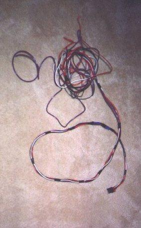
Completed
Wiring Harness for the Compass/Temp Display Unit
- The top piece is
covered in headliner fabric, which in my case did not match. (Get a
gray one if you can!) I removed the old fabric, which does not come
off easily, and then spent about an hour removing the glue/foam that
was left with 3M adhesive remover. What a mess. Note that if you get
the matching grey console from David, you can SKIP this step!!!
- Now you're ready
to fit the base. Hold it up in the position you want it (it fits
perfectly between the sunvisors, like it grew there) and draw a
pencil outline from the inside edge of the base.
-
Take a very sharp X-Acto knife or a mat knife with a new blade and
(gulp!) cut your headliner on the pencil line. Take care at the
front of the headliner near the rear view mirror because six wires,
for the mirror and its courtesy lights, run directly underneath it.
No need to cut past the dome light hole -- console fits flush past
where the dome light mounted. CUT CONSERVATIVE HERE : you can ALWAYS
remove more headliner material, but it is pretty hard to undo if you
cut too much! Also, take some of the bigger scraps here and set
aside : they are perfect for gluing later on the "inside" of the
upper console to fill in the gaps near the dome light (will be
obvious when you have the console).
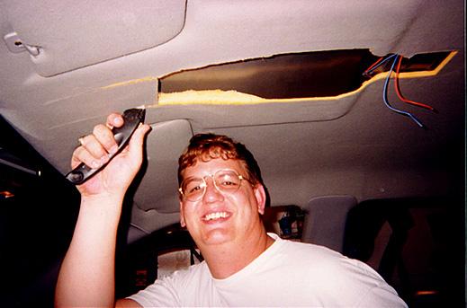
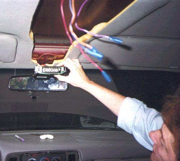
Ed Runnion
cutting his headliner. Yikes!!
- Fit the base up
into your new headliner hole and trim the edges of the hole until
the base fits snugly up into the hole. The sides of the Astro base
do not match the contour of the Impala headliner, but they slip
nicely up into the hole you've created so that the base fits almost
flush at this point.
- Remove the base
from the hole and trim the plastic front mounting boss so that it
matches the angle of the steel windshield header on the Impala --
it'll be at about a 45 degree angle. Once you've done that, the
console base should fit snugly up against the header and in your
newly cut hole.
-
Now
comes the tricky part -- you will need to fabricate a rear mounting
plate that attaches the center rib of the Impala roof (where the
dome light used to mount) to the two rear attaching points of the
console. I used an aluminum plate which I hacksawed to size and
drilled to two screws and 2 rivnuts. Two short sheet metal screws
held it up to the roof rib, and two rivnuts, mounted downward, so
the console mounting bosses, which are under the dome light lens,
would have a solid connection. Note : Ed Runnion got away with just
mounting the rear of the console directly to the cross-brace above
where the dome light USED to be, but still recommends doing it
David's way in hindsight.
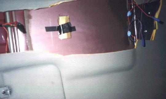
Pic of
mounting brace near domelight, wiring splices for light wiring, and
optional epoxied wood mounting base (for inside the CD Case) on
David Smith's car
- One more
scary part -- now I drilled into the windshield header, with visions
of slipping and making a nice ventilation hole in the outer roof
skin. I drilled a 3/8" hole and mounted a rubber-encased 10/32 nut,
the kind that cinch against the sheet metal as you tighten down. Use
a drill stop, which can be made from any old piece of tubing, to
limit your drill bit's penetrating length, and you'll remove any
worry of seeing sky. Then I mounted a short piece of threaded 10/32
rod in the rubber nut, bent it slightly so it would match the angle
of the mounting hole in the console, and used Loctite blue to make
sure it wouldn't back out. Note that Ed Runnion did this with a
10x1" sheetmetal screw WITH THE TIP CUT OFF and it worked fine just
drilling a small pilot hole for the screw (using a drillstop of
course!) and putting the screw in afterwards.
Kevin Headlee took another approach
to the above two steps. To quote from him : "I used 10-32 nutserts
in the roof braces at the windshield and roof light area. These work
great because if you are slightly off on your hole position you can
thread in a screw and use pliers to slightly bend the support to the
exact angle to match your hole. This will not distort the roof, and
allows for a factory quality mount that allows for fast console
removal. "
- Made my daily
pilgrimage to the parts store (Pep Boys) and picked up a roll of
headliner material, exact match for ours, for $7. (Such a deal!) Cut
it out along the same lines as the old piece, used spray adhesive
and in about 10 minutes had the console base covered. Make sure, if
you're as anal-retentive as I sometimes am, to cut the fabric on the
same bias as the Impala's headliner. (Tiny stripes in our head-liner
run from door to door, rather than from windshield to backlite, so I
matched this pattern on the console.) Note that if you got a
MATCHING console from David, you can SKIP this step!
- Now, wire in
connectors for the console lighting. Use either a 3 or 4 wire
connector that can be easily disconnected yet can handle the current
AND is also insulated (a 4-wire trailer lighting connector works
VERY well here), and then just "plug" in the console lighting while
mounting it. All of the lighting wiring is in the 4-pin black square
connector on the console. Snip off this connector, so you have just
the four wires from the console (orange, black, red, purple).
Solder up one end of the connector to the 4 wires from the console
(lighting harness). If you are using a 3-pin connector, then solder
both the red and orange wires in the console lighting harness to the
same pin on the connector (since both are gonna be the same signal
of +12V at all times).
Take the matching half of the connector and solder it up to the
following wires on the car, matching up the pins/signals of course!
Note this differs on the 94 Impala SS from the 95-96 Impala SS (not
sure on other B-bodies or other cars)
1994 SS
| COLOR of Wire in
the Console Wiring Harness |
FUNCTION of the
Wire |
COLOR of Wire to
connect it to on the car (cross-car lighting harness that runs
along the B-pillar roof brace) |
| BLACK |
FLOATING when
dome light is off, GND when it is on |
WHITE |
| PURPLE |
Ground at ALL
times |
DARK BLUE |
| RED |
+12V at ALL
times |
ORANGE |
| ORANGE |
+12V at ALL
times |
ORANGE |
1995-1996 SS
| COLOR of Wire in
the Console Wiring Harness |
FUNCTION of the
Wire |
COLOR of Wire to
connect it to on the car (cross-car lighting harness that runs
along the B-pillar roof brace) |
| BLACK |
FLOATING when
dome light is off, GND when it is on |
DARK BLUE |
| PURPLE |
Ground at ALL
times |
BLACK |
| RED |
+12V at ALL
times |
ORANGE |
| ORANGE |
+12V at ALL
times |
ORANGE |
- Time to install
the 6-wire console harness now. From console to radio, it will run
as follows : from the console front, along the front of the
headliner (tucked up in there) to the left A-pillar, down the
a-pillar (behind the trim), down thru the SMALL hole between the
a-pillar and dash, and then split with ONE wire (the longer purple
one) going out thru the grommet near the convenience center to
underhood, while the other 5 wires are tie-wrapped to the underdash
main harness to run towards the radio and eventually to the back of
the radio (whew!). Reread this a few times, and it'll make more
sense.
Start up at the top center of the headliner. Feed the black/red
connector thru your newly-cut hole in the center-front of the
headliner (with a few extra inches of wire to spare), and run the
wires under the headliner towards the left A-pillar. Once they come
out at the A-piller, reinstall the left sunvisor (3 screws). Next,
run the wires down the A-pillar, and then snake them thru the small
"gap" between the base of the pillar and the dash (my car had a
"foam block" here that simply pulled out to show the gap, other cars
may differ). Once the wires are thru this hole and are coming out
under the dash, reinstall the A-pillar trim (it just "snaps" back
into place).
Now, take the ONE longer wire (purple) and run it out into the
engine bay. Do this thru the rubber grommet that is located on the
firewall near the big plastic unit (convenience center) that holds
the flashers and a bunch of relays. If you haven't run a wire thru
this grommet before, take a SHARP punch or blade and put a small
hole in the grommet to feed the wire thru. Once the wire is fed
thru, it comes out on the firewall below the brake booster in the
engine compartment. Pull the wire thru completely, and tie-wrap it
underdash to other wiring if you can. Once in the engine
compartment, run it along the left fenderwell (either in existing
looms or factory looks) until it is alongside the PCM, and then run
it approx 1 foot further out and cut it.
Take the OTHER FIVE WIRES from the console, and run them along the
other underdash wiring bundle that crosses the bottom of the dash. I
zip-tied it to this bundle in 2-3 places so it would be secure. Once
you get it over to the radio, run it up to the back of the radio and
thru the hole in the back of the dash where the stock radio harness
runs. pull the wires thru snugly, and cut them approx 6" past the
front of the dash (this should leave plenty to work with).
- Now, time to hook
up the harness that you just routed. First, start with the purple
wire in the engine bay. If you look on the side of the PCM, there is
a connector on the side (C100 in the 96 Impala FSM) with 6 wires
into it. Two of the wires from the FRONT of the car into this
connector are LtGreen/Black and Yellow (Pins J & K). These wires run
to the temp sensor connector located at the front of the car near
the hood latch brace. You'll notice that there are NO wires coming
out of the back of this connector (towards the rear of the car) on
pins J & K.
Unplug this connector, and on the firewall-side connector pry off
the tab (either grey or tan, depending on the year of the car) on
the connector (prys from each side). Remove the "plugs" (little
rubber things) that are in pins J and K.
Take the blue connector (with approx 6 inch leads) that you cut off
of the console wiring harness above. Press in on the white tabs thru
the side, and remove the white plastic piece that helps hold the
wires in the connector. Using a paperclip, push in and "release" the
tabs (from the side of the connector with the pins) holding the
purple and green wire pins in the connector.
Now take these two wire/pins and put the purple one into Pin J of
the connector C100. Yes, it snaps right in!. Do likewise with the
green wire into Pin K. Once both pins are snapped in, seal them into
the connector with the silicone caulk, and reassemble the connector.
This is a bit of extra work, but give a nice "factory quality"
connection underhood for these signals.
Solder the PURPLE wire you ran from the console to the purple wire
put into Pin J on the connector C100 above. Then, solder a small
extension wire on the green wire on Pin K, and crimp a lug onto the
other end. Attatch this lug to a GOOD ground somewhere (I ran it to
the lug nearby above the headlamp unit). This completes the
underhood wiring. Also, plug in your Ambient Temp Sensor at this
time to the blue connector at the hood latch brace, and mount the
sensor on the brace so that it doesn't interfere with the hood,
latch, or grille (there is plenty of room to do this, it isn't
hard).
Now, time for the other five wires at the back of the radio. The
pins on the back of the radio are labelled 1-20, with the top row of
pins being 1-10, 11-15 being unused on the Impala (used to hook up
those neat steering-wheel controls and rear seat radios in other GM
vehicles), 16 being the VSS, and 17-20 being speaker wires. For
reference, this is pages 8A - 150 - 0 thru 8A - 150 - 7 in the 1996
FSM. Hook the wires from the compass to the radio wires as follows :
| PIN NUMBER
Black/Red Connector at Compass Display |
WIRE COLOR at
Compass Display |
PIN NUMBER at
the connector on the back of the Radio |
WIRE COLOR at
the connector on the back of the Radio |
| 5 |
BLACK |
9 |
YELLOW |
| 6 |
WHITE |
5 |
BLACK with
WHITE STRIPE |
| 7 |
GREEN |
16 |
DARK GREEN
with WHITE STRIPE |
| 9 |
ORANGE |
7 |
GRAY |
| 10 |
RED |
6 |
YELLOW (BROWN
in 9C1's) |
You can "lineman splice" the wires into the radio wires, or just get
lazy like I did and use the 3M "quick splice" connectors for these
wires.
Note that on the 94 SS, the Vss signal (Dark green with white
stripe, pin 16) is NOT in the radio harness. Instead, you need to
connect it to the Dark Green with White Stripe wire (also Vss) that
is in connector C200 under the dash (approximately above the drivers
right knee) at pin D8.
Shot of David Smith's Wiring Splices of the harness at the rear
of the radio.
-
Now, the point of "electrical truth" :^). Remove the compass display
from the currently disassembled console, and hook it up to the
black/red connector for it in the car. Reconnect the vehicle
battery. Turn the key on the either the "ACC" or "ON" position, and
your console display should now light up! Note that the compass will
probably NOT be correct : you will have to calibrate it later
according to the procedure listed below. Also, when you turn on the
parking/head lights, the compass display should dim just like the
radio display, and be adjustable in brightness. The temp displayed
should be correct, or at least pretty close (may be higher if you
are like me and the temp sensor was sitting in the sun before you
took this reading). Note that if you have an OPEN CIRCUIT problem
with your wiring, or the sensor is not connected, it will read "OC"
for the temperature. If you have a SHORT CIRCUIT problem, it will
read "SC".
Assuming that the console display works, turn off the key and unplug
the display (put it back in the console). Also, RE-DISCONNECT THE
BATTERY AT THIS POINT!!!
David Smith's Display unit passing the "Moment of Electrical
Truth"
- Reinstall the
radio (remember to plug in the harness and antenna!), and then
reinstall the lower dash.
- Put the console
back together -- it's lip will help hold the new material down. Then
test-fit it, trim as necessary, and mount. When you mount it, BE
SURE to plug in the compass/temp display as well as the map and dome
lights! I thought I needed one more mounting location, so I epoxied
a piece of oak to the inner roof panel, pre-drilled it to accept a
sheet metal screw, and then drilled a small hole in the inner panel
of the cd holder portion of the console. Note that Ed Runnion did
NOT need this extra mount point, and John "AK" Snyder did but put
his above the garage door opener holder instead. Use your best
judgement here.
-
Hook the battery back up, and test to make sure the dome and map
lights are all working.
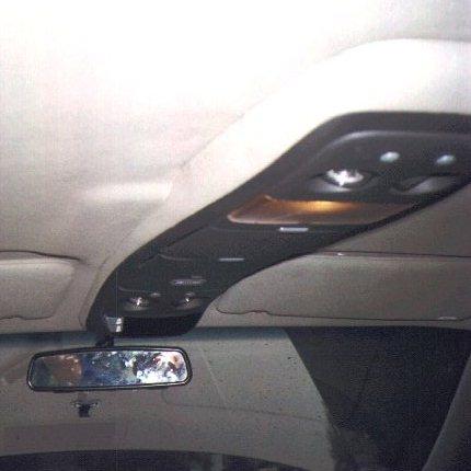
Another pic
of David Smith's installed console. Note that David covered the
"gaps" in the side of the console by CAREFULLY peeling back the
carpet at the gaps, putting in some "wood splints" there (made from
wooden kitchen sppons!), CAREFULLY re-gluing everything, and then
installing. Nice job!
- Assuming
everything works, now you need to go find a parking lot and perform
the following Compass Calibration Procedure (from a 96 DODGE Ram
manual of all places, but it works fine for us!) :
- Find a parking
lot where you can do some WIDE 360 degree circles. Heck, it'd even
work to drive around the edge of a parking lot. Important thing
here is you MUST be able to make at least 2-3 circles, and EACH
"circle" must take at least 15 seconds or so. In other words,
tire-smokin parking lot "donuts" will NOT work here, but you might
do a couple anyways just cause it is fun :^)!
-
Once you are ready to circle, press down the "on/off" button and
hold it. WHILE HOLDING THAT BUTTON, ALSO press the "US/Met" button
(so you are holding down BOTH buttons) for approx 5 seconds. The
display will say "var", which is your queue to set the "variance"
for the compass. You set the "variance" by releasing the buttons,
then hitting the "US/Met" button to scroll thru the different
variances. Once you get to the correct one, hit "On/Off" to set it
into the compass. A map showing the variance to be used for
various geographic locations is listed below.
- Next, repeat
step 2 again with the buttons, but this time hold the two buttons
PAST when the word "var" shows up, and eventually the word "cal"
will light instead. Once the word "cal" comes up, start your
driving in circles. After anywhere from 1 to 3 circles, the
compass will calibrate itself and the word "cal" will go out. Once
this happens, your compass is calibrated!
- Enjoy your
newly-installed and fully working Astrovan Overhead ConSSole Mod!!
|