Source:
http://www.impalassforum.com/vBulletin/showthread.php?t=274803
By: Live2Ride57
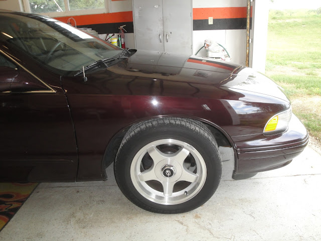
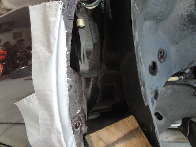
Looking at the project at
hand. Notice the antenna mast partially protruding from the fender.
The mast got bent, and it would only go partially up and down.
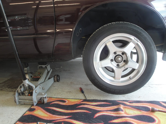
Removed the hubcap and loosened the lug nuts. Then jacked up the car,
removed the lug nuts and removed the tire.
Started removing the fender well bolts. There are five 10 mm bolts
along the edge of the wheel well.
Removed the three 13mm bolts inset in the wheel well.
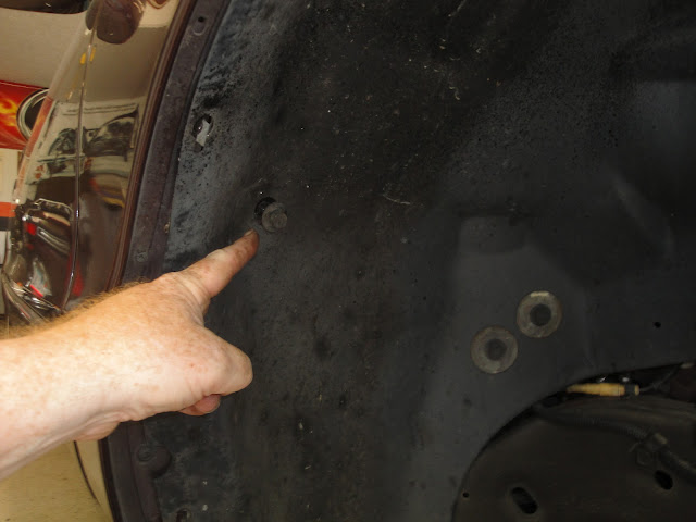
Then removed the three 10mm bolts with washers, inset the farthest in
the wheel well.
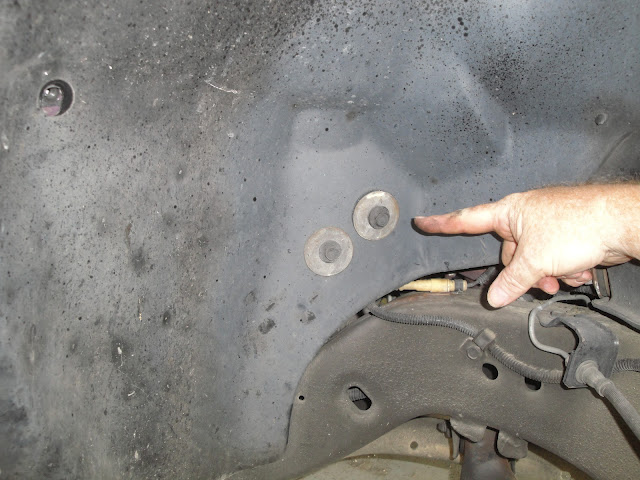
All the wheel well bolts removed. I don’t know if helped to remove the
forward most bolts, the wheel well was still very stiff when trying to
gain access.

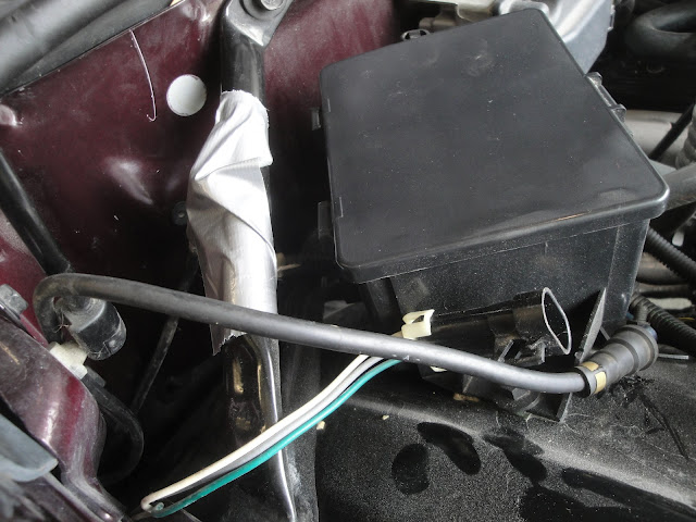
Opened the hood and unpluged the power and antenna connectors. I taped
the car side antenna wire to the brace so it wouldn’t fall down.
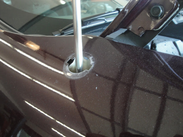
I removed the top nut and bezel. I used a needle nose plier and
positioned each jaw tip in a nut slot. Be very careful to not let
pliers slip and scratch paint as you rotate the nut.
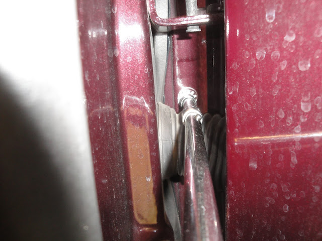
Then removed the 10mm bolt with star washer in the door jam. You’ll
hear the antenna drop.
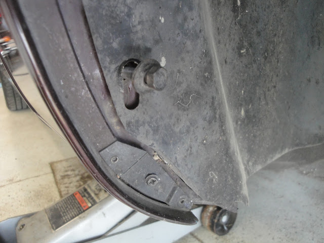
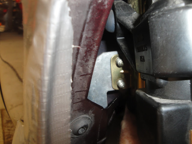
There it is! I propped the well back with a 2x4 to gain access. Notice
I taped the fender so I wouldn’t scratch the paint when I remove the
antenna.
.
It took some wiggling to get the antenna out. The bracket wanted to
catch on the fender brace.
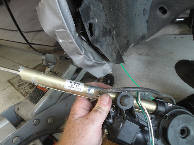
It's out!! The part number is different than the replacement I used. I
bought a used antenna from a 1992 B-Body, but it was identical.
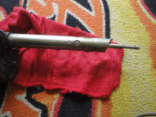
I tested the replacement antenna before installing. Propped it in the
engine compartment, plugged in the electrical connector and turned on
the radio – it went up, GOOD! Then I shut off the radio and unplugged
the connector with an inch or so of the mast still protruding from the
mast tube. This will help me to find the fender hole as I position the
antenna.
Up to this point I did everything alone. To install the antenna I got
a helper. That helped me get the mast through the fender hole and held
straight as my helper put on the bezel and screwed on the nut.
Now looking through the door I saw the antenna bracket and hole lined
up. My helper reinstalled the screw and star washer as I supported the
antenna from within. I now fed a weed wacker line down from the
engine bay and through the fender. I taped the power and antenna
wiring to the line, pulled them up and reconnected them to the car
side wiring, I retested the antenna and it went up and down – PERFECT!
All that was left to finish, was to re-install the wheel well bolts ,
put on the tire and lower the car. JOB DONE!

How to rebuild the Power Antenna
Source:
http://www.cadillacforums.com/forums/cadillac-tech-tips/169176-how-rebuild-power-antenna.html
Much thanks to "N*Caddy"
from Toronto, Canada for this guide!
In the last week I had
problems with my power antenna (or power mast). At some point refused
to retract.
Please be aware; if your power antenna is stuck immediately disconnect
the power harness from the relay mounted on the antenna. Remove the
liner to access the antenna and disconnect ANY of the two connectors
attached to the relay. If your antenna does not locks to the end of
the line (either fully extended or fully retracted) the battery will
be drained (even if fully extended or retracted does not means is
locked). Do not risk just disconnect one of the two connectors. If not
locked the motor receives continuously power and will drain the
battery (you can hear a low clicking sound once every 15-20 sec, that
is the bimetal safety switch connecting-disconnecting the motor). Also
the wires and the motor are warm to hot during this time (that is your
battery draining).
How to remove the antenna:
You need to disconnect the electrical connections (power and radio
antenna), the drain tube and unscrew (no 10 wrench) the ground wire
screw (topside) and the screw holding the antenna bracket to the body
(lower side). Then slide the antenna down (to clear the rubber
grommet). The antenna comes out from the trunk bracket attached.
Common problems to the antenna:
1. Burned Antenna fuse (20A trunk compartment)
2. Sticky antenna relay
3. Broken nylon wire lifting/lowering the antenna mast
4. Worn gears (motor shaft or plastic spooling wheel – worm screw
assembly)
5. Worn brushes
6. Burned/dirty locking contacts (part of the brushes assembly)
7. Sized motor shaft due to water intrusion
8. Burned motor
1 and 2 can be eliminated once the antenna is removed by applying 12V
([+] to pin A and [–] to pin B to extend mast or [+] to pin B and [–]
to pin C to retract mast) on the small pigtail harness connector that
goes from the relay to the antenna motor (to be seen in fig.1, is a 3
wires connector A – White wire, B – Green wire and C – Gray wire).
Never connect power between A and C (direct short)
If the mast is moving then either the antenna fuse is burned or the
antenna relay is sticky or wiring issue on the car harness.
3. Can be detected easily by trying to manually extend the mast, if it
extends then the wire is broken.
Any issue from 3 and down require disassembling the motor and gearing.
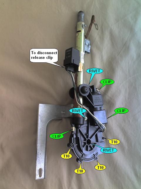
Fig. 1
In Fig.1 you can see the screw, clips and rivets holding the two
halves of the motor assembly together. If the antenna was never
serviced, from factory comes with rivets. You will need to drill the
rivets out and replace with screws. In my experience ½ inch long M5
screws with 2 washers are the best (you need 3).
Should you do exploratory surgery first, to prevent the wire from
coming loose from the gear, leave attached the plastic piece shown
removed in Fig.2.
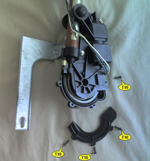
Fig. 2
Drill the rivets, pop the 3 clips and unscrew the one T10 screw not
holding the previously mentioned plastic piece.
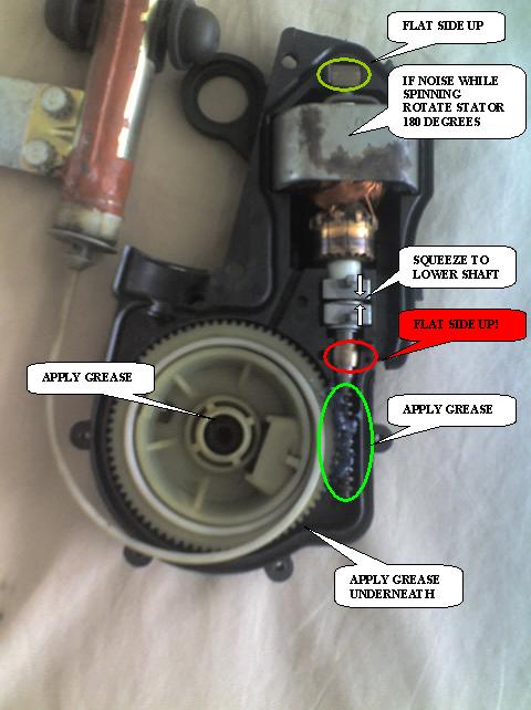
Fig. 3
In Fig. 3 is the inside of the antenna mechanism with the cover
removed. Please note the mast will come loose once the case is split
(as seen in fig 3).
Inspect for signs of worn gears on the worm screw assembly. Replace
the worn piece, if the shaft is rusted and worn then the whole motor
shaft has to be replaced. The motor shaft comes out from the plastic
casing after you take out the brushes/lock & safety switches assembly.
Inspect the brushes if worn replace assembly. The stator (the big
magnet shown in Fig. 3 should slide out (just magnetic force hold it
over the motor windings).
The shaft can be borrowed from ANY Delco power antenna motor used in
various GM models in the ‘90s. Fig. 4 is showing the stator.
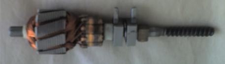
Fig. 4
The stator can be reused (just slide-it in place over the rotor). Note
on one side the stator has a small round rubber glued, that side
should be on the bottom (the not seen face in Fig. 3). To slide the
rotor in place squeeze the two locking switch actuators and lower
shaft. Make sure the two bushings (acting like bearings) are oriented
with the flat side UP. If the stator is rotated around the shaft with
the wrong side up then the motor will spin with grinding noise, if the
bushings are wrong side up the motor will spin slower (friction after
tightening the two halves of the plastic casing).
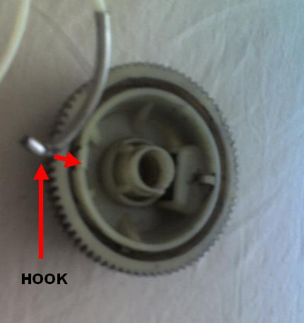
Fig. 5
If is only the plastic wheel then disconnect the hook attaching the
nylon wire to the wheel (as seen in Fig. 5) and replace wheel.
To attach the two halves of the case back together unwind the nylon
wire and position the wheel EXACTLY as shown in fig. 6.
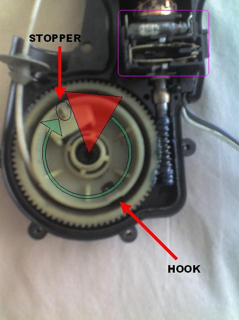
Fig. 6
Notice the notch called stopper, that notch can not be in the RED
area. Can be positioned in ANY position around that green circle but
better orient the wheel in the exact position shown in Fig. 6 with
minimum nylon wire on the wheel (notice the hook that is the end of
the nylon wire, less than ¼ of a turn).
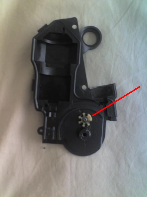
Fig. 7
Observe the small wheel on the cover (see Fig. 7). Make sure the wheel
is oriented in EXACTLY the position indicated (the missing tooth
should be towards the red line). That wheel is what stops the antenna
when fully extended. If the wheel is randomly oriented the antenna
will not extend all the way.
Lubricate with grease all points indicated in fig 3 and the area
around the little gear shown on fig. 6. Do not lubricate the cable or
the mast.
Slide the brushes/switched assembly over the shaft (as seen in fig 6
highlighted magenta). If brushes are loose re-gap as required, then
put the cover back along with the clips and screws (replacing the
rivets). At the same time make sure the round gasket over the nylon
wire (seen in Fig 3 and 6) is placed in the correct location.
ALWAYS do a bench test of the antenna; apply 12 V as described above.
Allow the mast to travel from fully retracted to fully extend (several
times). Very important, you should hear a distinctive click at the end
of the travel (in any direction). If no click, the shaft does not
slides (up or down) disconnecting the power to the motor. You can
observe the shaft sliding up or down with the cover removed (as seen
in Fig 2.). If no distinctive loud click start all over (something is
not assembled correctly).
Hope this will save you $50 or so. |