Thanks Buford T.
JuSStice for the credit of the idea. I usually need someone to
prod me to start something so thanks for that! Most of my information
I've learned was from going through the past forum threads about this,
Information from members of my local car club, doing the job 3 times
(cause I fooked up) and "TheFooserGuy"
---------------------------------------------------------------------- Symptoms of a bad waterpump:
http://www.impalassforum.com/vBulletin/showthread.php?t=248868
* Coolant coming out of the weep
hole (under the waterpump directly above your high $$$ opti) This is
the best sign
* Car overheating (There is a lot of causes of this but
this can be 1 of many)
* Leaks around clamped in pieces (Not around hoses but
metal to metal)
* Smell of antifreeze under the hood (FIND THE SOURCE!)
-----------------------------------------------------------------------
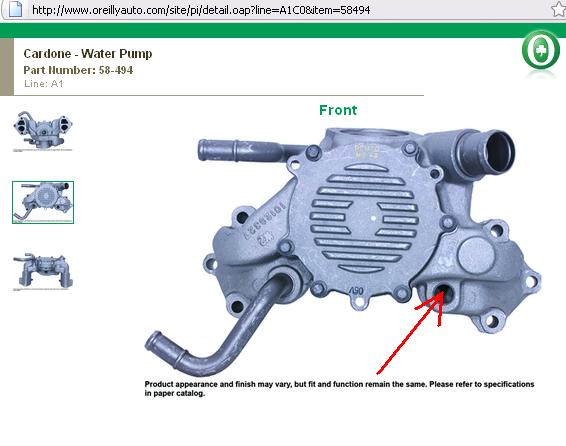
Which waterpump to get: (If you are NOT going
electric)
* Most autopart stores carry re-manufactured and *new*
waterpumps. I've experienced poor quality from both. As mentioned
above, check the fittings of the waterpump where the smaller hoses
(from the "T" fitting and heatercore) come into the pump. YOU
SHOULD NOT BE ABLE TO MOVE THESE. If you can, tell them you don't
want it. The piece will definitely leak out of this joint if you put
it on your car.
-----------------------------------------------------------------------
Which waterpump to get: (If you ARE going
electric)
* I have no experience with these. There are pros and
cons with going to an electric.
-----------------------------------------------------------------------
Installation Guide:
1. Read up on what you are going to do. Don't just look
here, read your FSM or other book that tells you how to do it as well.
Use common sense unless you don't have any, in which case you should
just take it to the shop and pay to get it done (Hopefully you have
more money than sense)
2. Get the car to where you want it and let it cool
(Hot coolant will burn you)
3. Ramp up car - Follow all typical safety procedures.
Don't jack your car up on a muddy driveway and get under it, etc...
4. Get your tools ready. You will need various metric
sockets to take off the waterpump bolts, towels and rags, a
screwdriver and other "scraping" devices, torque wrench, put the beer
in the fridge now (no beer till the job is DONE!)
5. Put a towel/rag under the waterpump and on top of
the opti to protect it from any coolant that will spash on it.
Antifreeze in opti = sad opti = $$$ = you not happy. In fact don't get
coolant anywhere except in the bucket. If you get it on the paint wipe
that stuff off with the quickness!
6. Make sure you have plenty of time to do what you
need to do here and don't rush or do a 1/2 ass job. I've done this 3
times because I didn't listen, thought I knew better, and just wanted
to get it done. This will cost you more time, money, and hassle that
no one has right now.
7. Drain the coolant. Take the cap off of the reservoir
tank. You don't "have to" drain it all but your already here and have
the bucket out so nut up and shut up and do it. Take the lower
radiator hose off and stick it in the bucket ASAP or your get your
shoes wet.
8. Drain the block. Pull the knock sensors and get all
of that crud out of there. This stuff can be nasty... (You may want to
fill your cooling system with water and remove the T-Stat to get some
more crud out. DO NOT DO THIS ON A HOT ENGINE. I'm not
responsible if you crack your block)
9. This is a great time to flush your heatercore (You
have to take the hoses off at the waterpump anyway) Guide to do that
is here : I really couldn't find a good thread I liked, someone
please find one for me thanks.
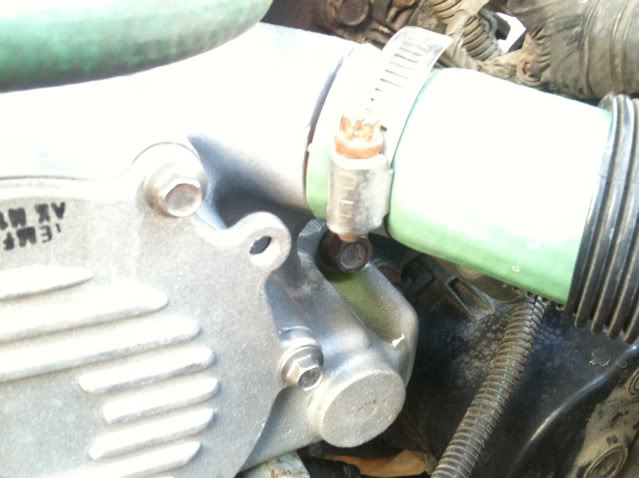
10. Disconnect all hoses going to the waterpump. (This
is a great time to upgrade your hoses too)
11. Remove the coolant temp sensor for the fans.
located below. Clean the threads with a wire brush, put blue thread
lock on it. Make sure you put it on the new waterpump so you don't
forget about it.
12. Remove the (6) bolts that connect the Waterpump to
the block. The exact size isn't coming to mind but you will need a
deep socket for these as I recall (or that is what I used)
13. Remove the waterpump (Should just pull out, only
gasket holding it in place)
14. Remove the thermostat housing (on top of the
waterpump) and thermostat. Put these in the new waterpump. DO NOT
OVERTIGHTEN THE BOLTS. I believe the FSM says 20lbs of torque, this is
incorrect, it should be 8lbs. If you start leaking from here after all
is said and done you can tighten them down a bit more but DO NOT
STRIP THE THREADS ON THE WATERPUMP (Especially after you have the
new one on your car, you will be pissed, ask me how I know)
15. scrap the gasket that stuck to the block off.
Don't be a pansy on this, when you think you got it good and clean
go over it again. This gasket it the only thing keeping the
pressurized coolant from leaking out. And it wants out SOOOO bad.
16. Clean the front of your engine. Your there, if you
have time give it a little TLC
18. Take a look at the bolts that hold the waterpump
on. Take a steel brush and clean the threads really good. (again,
don't be a pansy) You are going to need some blue thread lock.
IF YOU DO NOT PUT THREAD LOCK ON YOUR BOLTS THE COOLANT WILL SEEP UP
THE THREADS AND YOU WILL HAVE LEAKS/DRIPS Ask me how I know.
19. Take a break
20. Your ready to put the new pump on. You need to put
sealant on BOTH SIDES of the gasket. Don't be a pansy here
either. Your not making a grilled cheese sandwich, spread that
ish around to all the corners and edges. I find it's easier to (have
your dad do it but I watched him) stick it on one side, put that on
the waterpump, then put the sealeant on the otherside now that it is
attached to the waterpump.
21. Stick a few bolts in the waterpump and get those
bolts started on the block, use these to help guide the waterpump to
the right spot.
22. Bolt on the waterpump, follow the manual for torque
specs (I need to look this up later)
20. Connect all hoses and caps and plugs you took off
to drain.
25. Plug in the coolant temperature sensor. (Hope you
remembered to remove it and didn't leave it on the waterpump that you
returned to O'Rielly's yesterday for your core charge and it's 9PM on
a Sunday... Ask me how I know)
32. Look for leaks, smell for antifreeze (you may smell
some from have it dripping everywhere but it should go away in 24
hours unless you dumped it everywhere)
One of the greatest features of
the '92 and up Chevrolet LT1 engine is the reverse flow cooling
system. In fact it is reverse flow cooling that is truly the key to
the incredible performance of the modern LT1. Reverse flow cooling is
vastly superior to the conventional cooling systems used on virtually
all other engines. This is because it cools the cylinder heads first,
preventing detonation and allowing for a much higher compression ratio
and more spark advance on a given grade of gasoline. A fringe benefit
is that cylinder bore temperatures are higher and more uniform, which
reduces piston ring friction. Because of this new cooling system, the
LT1 can easily meet ever increasing emissions standards with
significant gains in power, durability, and reliability.
Conventional Coolant Flow:
In a conventional engine design,
coolant enters the front of the block and circulates through the
block's water jacket. The coolant is first heated by the cylinder
barrels, and then hot coolant is subsequently routed through the
cylinder heads and intake manifold before returning through the
thermostat to the radiator.
Because the coolant from the
radiator is first directed to the cylinder bores, they run at below
optimum temperatures which increases piston ring friction. The heads
subsequently get coolant that has already been heated by the cylinder
block, which causes the heads to run well above optimum temperatures.
The hotter cylinder heads promote detonation (spark knock) and head
gasket failures. To combat the increased tendency to detonate,
compression ratios has to be lowered and spark advance reduced, which
significantly reduces engine power output and efficiency.
Besides promoting detonation,
causing gasket failures, forcing reduced compression, spark advance,
and significantly reduced power output, a conventional cooling system
causes several other problems. Since the thermostat is on the exit
side of the system, it does not have direct control over the cold
coolant entering from the radiator. This is especially true when the
thermostat first opens after reaching operating temperature. As the
thermostat first opens allowing hot coolant to exit the engine, a rush
of very cold coolant enters the block all at once, shocking the engine
and causing sudden dimensional changes in the metal components. The
extreme thermal shock experienced by the engine causes head gaskets
and other soft parts to fail much more quickly.
Conventional cooling system
design also allows isolated engine hot spots to occur, which lead to
the generation of steam pockets and coolant foaming. Coolant which is
full of air and foam reduces cooling system performance and can even
lead to engine overheating.
LT1 Coolant Flow:
The LT1 is completely different
since it uses reverse flow cooling. The incoming coolant first
encounters the thermostat, which now acts both on the inlet and outlet
sides of the system. Depending on the engine coolant temperature, cold
coolant from the radiator is carefully metered into the engine. This
allows a more controlled amount of cold coolant to enter, which
immediately mixes with the bypass coolant already flowing. This
virtually eliminates the thermal shock present in the old system.
After entering through one side
of the 2-way thermostat (at the appropriate temperature), the cold
coolant is routed directly to the cylinder heads first, where the
combustion chambers, spark plugs and exhaust ports are cooled. Then
the heated coolant returns to the engine block and circulates around
the cylinder barrels. The hot coolant from the block re-enters the
water pump, and hits the other side of the 2-way thermostat, where it
is either re-circulated back through the engine or directed to the
radiator, depending on temperature.
All of this means that the
thermostat housing is the INLET (opposite of most engines), while the
water pump is the OUTLET. The water pump (outlet) on the engine runs
to the top left (inlet) of the radiator. The lower right (outlet) of
the radiator runs to the thermostat housing (inlet) on the engine.
This also means that the "upper"
hose on the radiator would be connected to the water pump (mid/lower
part of the engine) and is the outlet of the engine, so it should be
hot with the thermostat open. The lower hose on the radiator is
connected to the thermostat housing (upper part of the engine) and is
the inlet to the engine.
The main concept behind reverse
flow cooling is to cool the heads first, which greatly reduces the
tendency for detonation, and is the primary reason that the LT1 can
run 10.5 to 1 compression and fairly significant ignition advance on
modern lead-free gasoline. Reverse flow cooling is THE KEY to the
Generation II LT1s increased power, durability, and reliability over
the first generation smallblock engine.
There are three main circulation
systems for the LT1, while most engines only have two systems. As with
most cars there is circulation through the heater core and the
radiator, but there is a third system on the LT1 which includes steam
vents in the head, along with a pressurized reservoir.
Coolant to the heater core comes
from the water pump. The lower hose on the water pump is the heater
core inlet, and should have a flow restrictor mounted in the hose.
This is to prevent over-stressing the core at high engine rpms. The
heater core outlet hose returns to the water pump at the upper hose
connection, and also has a T-connector to the pressurized reservoir to
bleed off any air.
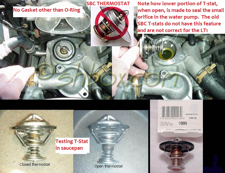
Thermostats:
All LT1 engines utilize a
special 2-way acting full bypass thermostat which can be seen in this
photo:
. Dual-acting means
that the thermostat regulates coolant flow both in to as well as out
of the engine, while the bypass portion of the thermostat circuit
supplies the water pump with a full flow of liquid coolant at all
times. This is unlike a conventional engine thermostat, which only
regulates coolant flow at the engine outlet, and which does not allow
full flow through the water pump when the engine is cold and the
thermostat is in bypass mode.
Both sides of the 2-way
thermostat used in the LT1 are linked together, and a single wax
pellet actuator operates the spring loaded mechanism at a pre-set
temperature. When the designated temperature is reached, the wax
pellet expands, opening the dual acting valve. All current LT1s come
from the factory with a relatively low 180 degree temperature
thermostat. Most conventional engines today use 195 degree thermostats
in order to meet emissions specifications at the expense of power,
durability, and reliability.
It is important to note that the
2-way thermostat is unique to the Generation II LT1 and is not
interchangeable with older Chevrolet smallblock engines. This is
particularly important if you decide to change to a colder 160 degree
thermostat, make sure it is the proper dual acting type required by
the modern LT1. You can obtain the proper type in a 160 degree version
from
or
.
Additional LT1 Cooling System
Improvements:
In addition to reverse coolant
flow, there are several other improvements in the LT1 cooling system
over conventional engines.
Dry Intake Manifold:
The LT1 has absolutely NO water
running through the intake manifold! Conventional cooling systems have
passages in the intake manifold which allow coolant to crossover from
one side of the engine to the other. In the LT1, coolant crossover
occurs in the water pump, which is also where the thermostat is
located. Since there are no coolant passages in the intake manifold, a
major source of leaks has been eliminated. Overall engine reliability
is improved since an intake manifold leak allows coolant to enter the
top of the engine which can quickly wipe out the camshaft, lifters,
and other major engine components. Designing a dry intake manifold
without either coolant passages or a thermostat housing also allows a
much lower profile. The LT1 engine is 87mm (nearly 3.5 inches) lower
than the previous L98 Corvette engine.
Gear Driven Water Pump:
One big problem with
conventional cooling systems is the water pump, which simply cannot
last a targeted minimum 100,000 mile reliability figure without
experiencing leaking gaskets or seal failures. This has traditionally
been caused by the excessive side loads placed on the bearings and
seals of a conventional water pump through the belt drive mechanism.
In the LT1 this problem is solved by driving the water pump directly
via a spur gear driven by the camshaft sprocket. This results in a
dramatically more reliable water pump that should easily last 100,000
miles or more.
Since the water pump is no
longer belt driven, the vehicle will still be driveable even if the
serpentine belt fails. This is a major safety factor as it allows one
to drive the partially disabled vehicle to the nearest service center.
Steam Vents:
The LT1 has strategically placed
steam vents at the back of both cylinder heads. Since the heads are
the hottest part of the engine, pockets of steam can be more easily
generated there. The steam vents are connected together by a crossover
vent tube at the back of the heads, which directs any steam and a
small flow of coolant to the front of the engine where it flows
through the throttle body, warming it for improved cold weather
performance. After passing through the throttle body, most of the
steam is condensed back into liquid coolant and returned to the
system.
In LT1 B/D-cars, coolant exiting
the throttle body is passed directly into a pressurized coolant
reservoir where any air remaining in the coolant is completely
scavenged. In LT1 F-cars, coolant from the throttle body connects to
the heater outlet via a vented "tee" connector, where any trapped air
in the system can be bled off manually. Eliminating steam pockets and
foam in the coolant allows for more uniform cooling system
performance, preventing hot spots and potential overheating.
Radiator Flow:
The radiator is a standard
cross-flow type with coolant entering on the left and exiting on the
right. Unlike a conventional cooling system, the thermostat housing is
the inlet for the engine and is therefore connected to the outlet at
the radiator. The upper left (inlet) side of the radiator is connected
to the water pump (outlet) on the engine, and the lower right (outlet)
side of the radiator is connected to the thermostat housing (inlet) on
the engine. Flow through the engine is reversed, however flow through
the radiator is conventional.
Precision Machined Thermostat
Housing:
The thermostat housing is a
precision machined component that fits directly onto the top of the
water pump without a gasket. Instead, an O-ring is used to seal the
thermostat inside the housing. This precision design reduces the
tendency for leaks, plus it makes thermostat replacement a very simple
job since there is no old gasket material to scrape off. Servicing is
further simplified because the thermostat housing is situated directly
on top of the water pump, and access is unobstructed. I dare say that
the LT1 thermostat is the easiest to change I have ever experienced.
Finally, an air bleeder valve is located on the top of the thermostat
housing, which allows one to quickly and easily bleed out any trapped
air after cooling system maintenance has been performed.
Some Tips For Replacing The
Thermostat:
Follow the service manual
procedure, but beware of a few things. One is that despite the drawing
in the service manual, there is no gasket. There is an O-ring seal
that goes around the thermostat itself, which should come with the
thermostat.
Also beware that the factory
manuals and any instructions written from them show an INCORRECT 21
ft-lb. torque spec. for the two thermostat housing bolts. Noting that
these are tiny 5mm bolts in an aluminum housing, it was obvious to me
that the specification was wrong (nearly three times too much), but I
know several people who have tried to tighten to that spec, stripping
both bolt holes instantly, requiring a helicoil repair.
ALL '94-'96 B-car and F-car
manuals list this incorrect torque spec! The correct spec., which is
reported in the updated '96 'vette manual is 89 in-lb. or 7.4 ft-lb.
I'm surprised there are not more people busting these bolts or
stripping out the threads in the aluminum water pump housing. GM
should really issue a TSB on this!
A final concern is that you
should pack the area below the thermostat housing and above the
distributor with rags before undoing anything. The distributor is
mounted low on the front of the block, behind and between the water
pump and above the crankshaft, and you do not want coolant dripping
onto the distributor. If any coolant enters the distributor, it will
likely cause accelerated corrosion and require the distributor be
repaired or replaced.
Low Operating Pressure:
The entire cooling system on the
LT1 is designed to operate at lower pressures than conventional
cooling systems. The maximum operating pressure in the LT1 cooling
system is 15 psi for B/D-cars and 18 psi for F-cars, limited by a
pressure cap. These limits are similar to other cars, but in the LT1,
these maximum pressures are rarely reached. Running at a lower
pressure drastically decreases the number of leaks and significantly
improves overall reliability and durability.
Coolant Reservoir:
Corvette and B/D-car LT1
applications use a pressurized coolant recovery reservoir instead of a
non-pressurized overflow tank used with conventional cooling systems.
All of the coolant flows continuously through the pressurized
reservoir, which is an integral part of the cooling system. The
pressurized reservoir in the LT1 B/D-cars is connected to the cooling
system in three places. One inlet hose connects to the top of the RH
radiator tank, a second inlet hose is attached through a "tee"
connection on the heater inlet hose, and a third outlet hose is
connected to a "tee" connection in the throttle body heater outlet.
The pressurized reservoir is
mounted at the highest point in the system, and provides a place where
all air can be continuously scavenged from the coolant. Any steam and
bubbles are allowed to rise to the surface, eliminating foam and
providing pure liquid coolant back to the engine. Pure liquid coolant
is returned to the system via the heater outlet hose connection. The
pressure relief/vent cap in these systems is rated at 15 psi and is
located on the reservoir rather than the radiator.
LT1 F-cars use a conventional
coolant recovery system which consists of a non-pressurized coolant
overflow tank connected to the radiator by a single hose. These cars
use an 18 psi rated pressure relief/vent cap on the radiator like most
conventional systems. Since these cars cannot scavenge air from the
coolant as well as the B/D-car or Corvette systems, they have two air
bleeder valves for manually bleeding trapped air from the system. One
is in the thermostat housing, which is the same as all other LT1
engine vehicles, and the second one is located in a "tee" where the
coolant from the throttle body connects to the heater return hose.
Standard equipment for all LT1
equipped B/D-cars is a dual electric fan setup with a 150-watt primary
(RH) fan and a 100-watt secondary (LH) fan. The electric engine
coolant fans are independently operated by the PCM (Powertrain Control
Module) based on the inputs from the Engine Coolant Temperature (ECT)
sensor, A/C Pressure Sensor, Vehicle Speed Sensor (VSS), and various
other inputs.
The B/D-car coolant fans operate
under PCM control at the following engine temperatures and A/C system
pressures:
Fan
Mode
Temperature
A/C
Pressure
Primary (RH) Fan ON
109 C
229 F
189
psi
Primary (RH) Fan OFF
105 C
221 F
150
psi
Secondary (LH) Fan ON
112 C
234 F
240
psi
Secondary (LH) Fan OFF
108 C
227 F
210
psi
Additionally, the PCM will turn off the
fans at higher vehicle speeds (above 48 MPH I believe) since running fans can
actually impede airflow through the radiator at high speed. Each fan also has a
minimum running time. Once activated, the primary fan will run for a minimum of
50 seconds, and the secondary fan for a minimum of 26 seconds. Finally, certain
Diagnostic Trouble Codes (DTCs) may cause the PCM to turn on one or both fans.
All LT1 B/D-cars have two
transmission oil coolers and an engine oil cooler as standard
equipment. The transmission coolers include a primary oil to water
type inside the RH radiator tank, and a secondary external oil to air
cooler (KD1) mounted in front of the radiator on the RH side. The
external KD1 cooler is an aluminum stacked plate type cooler painted
black with metal tube lines linking it in series with the other cooler
in the radiator tank. LT1 B/D-cars also include an engine oil to water
cooler (KC4) mounted in the LH radiator tank.
Optional B/D-car LT1 Cooling
Systems:
There are two optional cooling
system upgrades for LT1 B/D-cars, called V03 (Extra Capacity Cooling),
and V08 (Heavy Duty Cooling). Performance models such as the WX3
(Impala SS) and 9C1 (Police) cars automatically get the upgraded V03
(Extra Capacity Cooling) system. V03 includes a larger radiator, an
increased capacity A/C condenser, and an upgraded secondary electric
fan. V03 is also optional on most B/D-car models.
Note that the '94 V03 (Extra
Capacity Cooling) option uses a 150-watt primary (RH) fan, and an
upgraded 240-watt secondary (LH) fan. In '95-'96 the V03 package was
revised and no longer included an upgraded 240-watt secondary fan.
Instead the standard 100-watt secondary fan was used, which is the
same as the base cooling system.
B/D-cars other than the Impala
SS or Police package Caprice also have an optional V08 (Heavy Duty
Cooling) package which is part of the V92 (Trailer Towing) package.
V08 includes the larger radiator, increased capacity A/C condenser,
and upgraded secondary fan as in the V03 system, however it differs in
the primary cooling fan. With V08 the 150-watt electric primary fan is
replaced by a mechanical belt driven thermostatic clutch fan. To drive
the mechanical fan, the V08 system includes a crank pulley, belt
tensioner and bracket, and a large radiator shroud in addition to the
mechanical fan itself. This package is not available on the WX3
(Impala SS) or 9C1 (Police) cars since the mechanical fan is driven by
an additional pulley and belt on the engine crankshaft, which draws
engine power thus reducing performance.
The mechanical fan used
with the V08 cooling system contains a built-in thermostatic clutch
which senses the temperature of air that has been drawn through the
radiator. When the temperature of this air is below 66 degrees C (151
degrees F), the clutch freewheels and limits the fan speed to
800-1,400 rpm. When the temperature rises above 66 degrees C (151
degrees F), the clutch begins to engage, and the fan speed increases
to about 2,200 rpm. The RH radiator hose in V08 equipped vehicles has
a steel tube section near the fan designed to prevent damage in case
of fan contact.
There are several SEO (Special
Equipment Option) B-car ooling options which are included as standard
only with 9C1 (Police) package Caprices. These include the following:
In addition to the standard
inclusion of the V03 (Extra Capacity Cooling) package, all LT1 Caprice
9C1 (Police) cars also include SEO 1T1 (Silicone Radiator and Heater
Hoses). SEO 1T1 consists of special green radiator and heater hoses
made out of pure silicone rubber. These hoses are designed to last the
life of the vehicle and never need replacement unlike the standard
black rubber hoses. SEO 1T1 also includes heavy duty stainless steel
worm gear hose clamps which replace the standard squeeze type hose
clamps. The clamps have a solid full perimeter band, which prevents
the hose from extruding between the slotted area where the screw fits.
This also prevents the hose from being cut or damaged by the clamp,
and allows a more even sealing force around the entire clamp
perimeter.
The 9C1 Police package also
includes SEO 7P8 (External Engine Oil to Air Cooler). This is an
unpainted aluminum stacked plate type cooler which is mounted in front
of the radiator on the LH side opposite the external transmission
cooler. This heavy duty engine oil cooler replaces the standard engine
oil to water cooler found in the LH radiator tank of other LT1 B-cars.
Also included with the Police
package is SEO 7L9 (Power Steering Fluid Cooler). This consists of a
loop of metal tubing installed between the radiator lower support and
the front stabilizer bar. This cooler prevents the power steering
fluid from overheating in rigorous driving situations such as high
speed pursuit.
F-car LT1 (Camaro/Firebird)
Cooling Systems:
Standard equipment for all LT1
F-cars with A/C is a dual electric fan setup with primary (LH) and
secondary (RH) fans. There are two different wiring schemes used for
these fans, an early design that was used in '93-'94 and a late design
that has been used from mid-'94 up. Note that non-A/C F-cars have a
single primary fan which operates at a fixed high speed.
In '93 and early '94 models with
A/C, the two cooling fans are independently operated by the PCM
(Powertrain Control Module) at a high fixed speed by using a single
relay for each fan. Late '94 and newer F-car models operate both fans
simultaneously in either a low or a high speed mode by using 3 relays.
In low speed mode, the fans are powered in series. In high speed mode,
the relays operate to power both fans in parallel, resulting in a
higher speed of operation.
One way to tell which setup you
have is by looking at the alternator. If an F-car is equipped with the
124 amp alternator (KG7), then the vehicle has the early design setup
and the fans are operated independently. If the vehicle has the 140
amp alternator (KG9), then it also has the newer design configuration
which operates the fans simultaneously in low or high speed modes.
The PCM operates the coolant
fans based on input from the Engine Coolant Temperature (ECT) sensor,
A/C Pressure Sensor, Vehicle Speed Sensor (VSS), and various other
inputs. The F-car coolant fans operate at the following temperatures
and pressures:
Fan
Mode
Temperature
A/C
Pressure
Primary (LH) or Dual Low-speed Fan(s) ON:
108 C
226 F
248
psi*
Primary (LH) or Dual Low-speed Fan(s) OFF:
105 C
221 F
208
psi*
Secondary (RH) or Dual High-speed Fan(s) ON
113 C
235 F
248
psi
Secondary (RH) or Dual High-speed Fan(s) OFF:
110 C
230 F
208 ps
*Note - this information is
probably incorrect, although it is quoted from the service manual.
Additionally, the PCM will turn
off the fans at higher vehicle speeds (above 70 MPH I believe) since
running fans can actually impede airflow through the radiator at high
speed. Each fan or fan mode has a minimum running time. Once
activated, the primary fan or dual low-speed fans will run for a
minimum of 50 seconds, and the secondary or dual high-speed fans for a
minimum of 30 seconds. Finally, certain Diagnostic Trouble Codes
(DTCs) may cause the PCM to turn on one or both fans.
All LT1 F-cars with automatic
transmissions also have a transmission oil cooler as standard
equipment. The transmission cooler is an oil to water type mounted
inside the RH radiator tank.
Optional F-car LT1 Cooling
Systems:
There is only one option in an
LT1 F-car with respect to cooling, and that is an engine oil cooler
(KC4). The engine oil cooler is an oil to water design that is mounted
in the LH radiator tank. The KC4 oil cooler is included with various
other combinations of options on the F-cars.
Operating Characteristics and
Observations:
I have an accurate digital
temperature gauge installed in the RH cylinder head water jacket on my
'94 Impala SS. I installed a brass "T" fitting in the RH cylinder
head, in the tapped hole where the factory temperature gauge sender
was originally installed. This allowed me to install both the original
analog gauge sender as well as the sender for the new digital gauge.
With the stock 180 degree thermostat, cruising at 80 mph on a cool
night I would routinely measure coolant temperatures in the head as
low as 167 degrees! If I slowed down, the temperature would climb up
into the 170-180 degree range depending on ambient temperatures and
cruising speed. The temperature would run in the 180s-190s cruising
more slowly on a hot summer day. In heavy stop and go traffic, the
temperature would quickly climb up into the 220-230 degree area, which
is where the primary fan starts to come on.
Many have noticed as I have that
the engine will actually run cooler in traffic with the A/C on. This
is because turning on the A/C will also cause the PCM to activate at
least the primary fan, and possibly the secondary fan (depending on
A/C system pressure) as well.
The radiator and A/C condenser
in B/D-cars equipped with the RPO (Regular Production Option) V08
(Heavy Duty Cooling) or V03 (Extra Capacity Cooling) systems are
extremely large, perhaps the largest of any passenger car on the
market today. The cooling and A/C system performance on these cars are
outstanding, in fact the best I have seen on any vehicle.
Recommendations for Cooling
System improvements:
If you have a B/D-car, there are
several easy improvements you can make by simply adding the cooling
related SEOs (Special Equipment Options) from the 9C1 Caprice Police
package. For example, I have installed all of the Police package
cooling upgrades in my '94 Impala SS. This includes the 1T1 silicone
hoses, 7L9 power steering fluid cooler, and 7P8 external engine oil
cooler. Combined with the already powerful V03 cooling system, these
factory upgrades combine to form the most extreme duty factory cooling
system present on any automobile I have seen.
If you have an F-car which was
not factory equipped with the optional KC4 engine oil cooler, then I
would highly recommend installing it as an upgrade. The KC4 option
consists of a different radiator with the engine oil cooler located
inside the LH tank. An adapter installs on the oil filter pad between
the filter and the engine, and lines run to the cooler in the radiator
tank.
There are two other cooling
system improvements that can be applied to any vehicles with the LT1
engine, including the Corvette and F-cars (Camaro/Firebird). These are
to change to a colder 160 degree thermostat (180 is standard), and to
alter the electric cooling fans to come on at a lower temperature.
This latter function can be accomplished by adding an external
thermostatic switch to the fan circuit, or by re-programming the PCM
fan operation settings.
Bypass Throttle Body:
You can bypass the throttle body
for a cooler (denser) air charge (and more power), but the line from
the steam vents *must* be connected to the reservoir, and the
reservoir to the heater hoses as well. Without the steam vents you
will have steam pockets and trapped air building up in the heads,
which will cause spot overheating. This will result in blown
headgaskets and other problems.
Fan Activation:
As mentioned earlier in this
article, the stock fans do not come on until at least 225 degrees,
which I feel is too hot. To prevent the engine from heating up this
high in traffic or while moving slowly, I installed a 203 degree GM
thermostatic switch (p/n 3053190) in a pre-existing tapped hole in the
LH cylinder head water jacket, and wired it to both the primary and
secondary fan relay via a 3-position toggle switch.
When the coolant temperature
reaches 203 degrees, the primary or secondary fan (depending on the
setting of the toggle switch) will run. This prevents the engine from
running hotter than about 200 degrees or so. I have tested this
modification in 100 degree ambient temperatures, while trapped in stop
and go traffic, and never saw coolant temperatures higher than 205
degrees. I wired the toggle switch to operate either the primary or
secondary fan, as well as to disconnect the thermostatic switch from
the circuit, thus disabling this function. No matter what the toggle
switch setting, the PCM still has control over the fan relays, and
will continue to operate the fans oblivious to the additional
thermostatic switch function.
As an alternative to the GM
switch, I have found a company that makes higher quality switches in a
variety of temperature settings that work as a direct replacement for
the GM switch:
John Flagg
GMP Parts Company
9901 Kent Street Suite #2
Elk Grove, CA 95624
(916) 685-1055
(916) 685-3139 FAX
GMP has the highest quality
switches available in a number of different temperature ranges so you
can pick whatever temp you want the fans to go on. I don't recommend
going lower than 185 degrees on the switch with a 160 degree
thermostat or the fans will likely remain on all the time. This is
because normal engine operating temperature is up to 20 degrees or
more higher than the engine thermostat setting.
I have more recently purchased
the Hypertech Power Programmer, which re-programs the PCM to turn the
primary fan on at 176 degrees (instead of 225), and the secondary fan
on at 191 (instead of 232). At first I installed the Hypertech program
without the recommended 160 degree thermostat in order to observe the
operation of the fans. I found that the primary fan would run
continuously once the engine had warmed up, and even the secondary fan
would be on most of the time. This is due to the overlap between the
high thermostat setting and the lower fan activation temperatures
programmed in by Hypertech. The new settings were turning the primary
fan on at a setting lower than the thermostat itself would open.
Another alternative over the
Hypertech device is to simply have your PCM reprogrammed by a service
such as that offered by my friend Ed Wright at Fastchip
. He can not only reprogram your fans, but can also
optimize many other areas of the PCM programming, adding power and
driveability. Tell Ed I sent you if you call. Reprogramming by
offers much more in the way of customization than
using the fixed calibrations in the Power Programmer.
After installing the recommended
160 degree thermostat, the fans worked normally, and would only begin
to run after the car was not moving which allowed the temperature to
rise. In actual operation I saw temperatures while moving about 10
degrees lower than what I observed with the 180 degree thermostat.
While moving very slowly or sitting stationery, the engine would never
climb above the low 190 range, no matter how high the ambient
temperatures was or how slow I was moving. After observing this
operation, I would wholeheartedly recommend the 160 degree thermostat
and the Hypertech Power Programmer. If you use the Power Programmer,
then the 160 degree thermostat MUST be installed or the fans will run
continuously, which is not good for either the fans, alternator, or
battery.
If you do not want to purchase
the (fairly expensive) Power Programmer, then I highly recommend
installing the 203 degree thermostatic fan switch I listed, which will
prevent the excessive temperatures encountered in traffic that are
allowed by the stock PCM program settings. The fan switch will work
well with either the stock 180 degree thermostat or a 160 degree unit,
and will limit the maximum coolant temperatures to 205 degrees or
less.
GM Vehicles Featuring the
Generation II LT1:
Chassis
Models
Years
Y-car
Corvette
'92-'96
F-car
Camaro/Firebird
'93-'97
B-car
Caprice/Impala/Roadmaster
94-'96
D-car
Fleetwood
'94-'96
Note that the D-cars are really a slightly stretched version of the B-car and are virtually identical except for the wheelbase.
If you have any
questions or comments concerning this article, I can be reached
at: Scott Mueller scottmueller@compuserve.com
Mueller Technical Research